Overview
|
As a side project, I designed a robotic arm in SolidWorks. I wanted to challenge myself with a project combining electrical, software, and mechanical engineering, specifically in mechanical. I wanted to take the information I have learned from my classes so far to create a robot. As I am interested in robots with a helping purpose, I settled upon a robotic arm. Not only can adults program it to retrieve objects for them nearby, kids can also play with it as an educational tool to interest them in robotics.
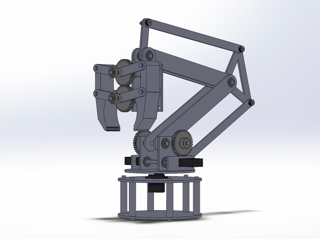
It uses four motors, and has four degrees of freedom. One motor is between the stand moving the entire assembly in the z axis (waist rotation), two at the base moving the arm backwards and forwards (shoulder rotation), up and down (elbow rotation), and one for opening and closing the claw (gripper rotation). Each piece of the claw is part of a four-bar linkage design, and the gears used are 18 and 36 tooth gears. |

|
Arm
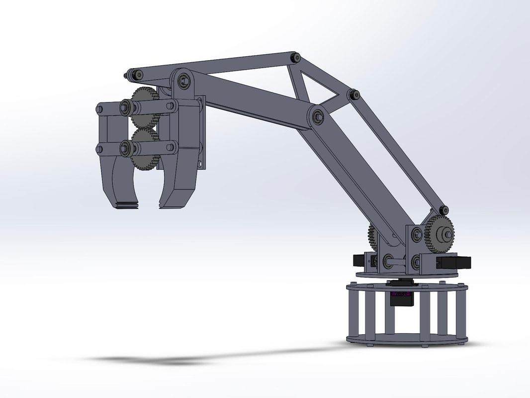
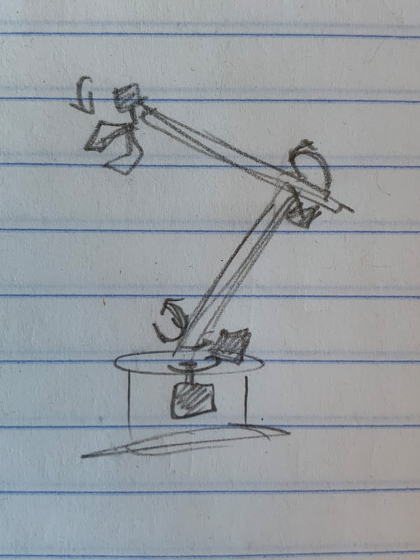
My first thought was to use four motors, each directly controlling the movement of a certain motion without extra linkages - waist, shoulder, elbow, gripper - but ultimately went with a linkage design, connecting all components of the arm to move together and more smoothly as a unit. While the motor on the left turns the vertical vertical arm moving it backwards and forwards (shoulder rotation), the motor on the right links to the horizontal arm on top moving the claw up and down (elbow rotation).
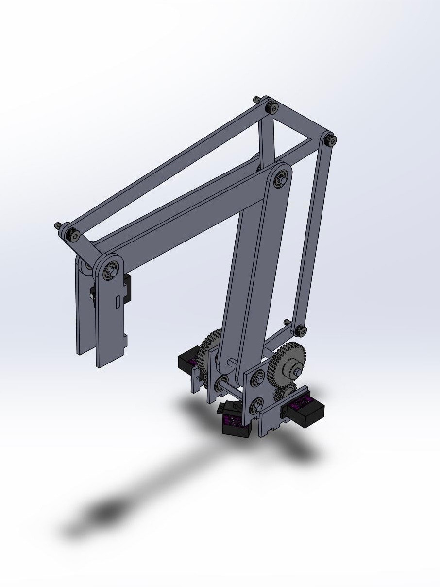
You can also see from the SolidWorks model above where the four motors are positioned and how they would move the arm.
Claw

|
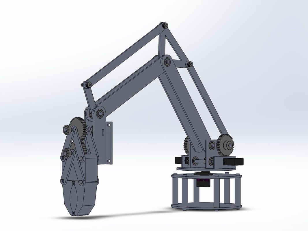
The motor for the claw powers two gears, each connected to a shaft which moves a piece of the claw. The claw itself is positioned to always face down with the weight of gravity and does not rotate on the x and y axis, only moving up and down with the arm. Although it would have been smart to add another motor to spin the claw in the z-axis, I did not add one as I was thinking about user simplicity with less motors and easier control.
The flat parts of the claw have indents for a better grip on the object. The gearing ratio is 1:1 with 36 tooth gears. |
Deeper Dive
I modeled the robotic arm so most pieces could be laser cut out of 1/8" material, and D-shafts and clock-cage posts made with a mill or lathe. The two halves of the gripper are meant to be 3D printed. Additionally, the structure is designed to be powered by four continuous rotation servos that are easily connected to and coded in Arduino.
If I were to expand on this project, I would re-design the claw to give the robotic arm a fifth degree of motion to grab objects parallel to the ground, and add a car-like base below so the claw can move around, all using a remote control device.
If I were to expand on this project, I would re-design the claw to give the robotic arm a fifth degree of motion to grab objects parallel to the ground, and add a car-like base below so the claw can move around, all using a remote control device.