Overview
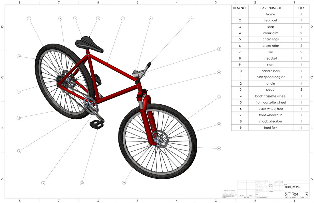
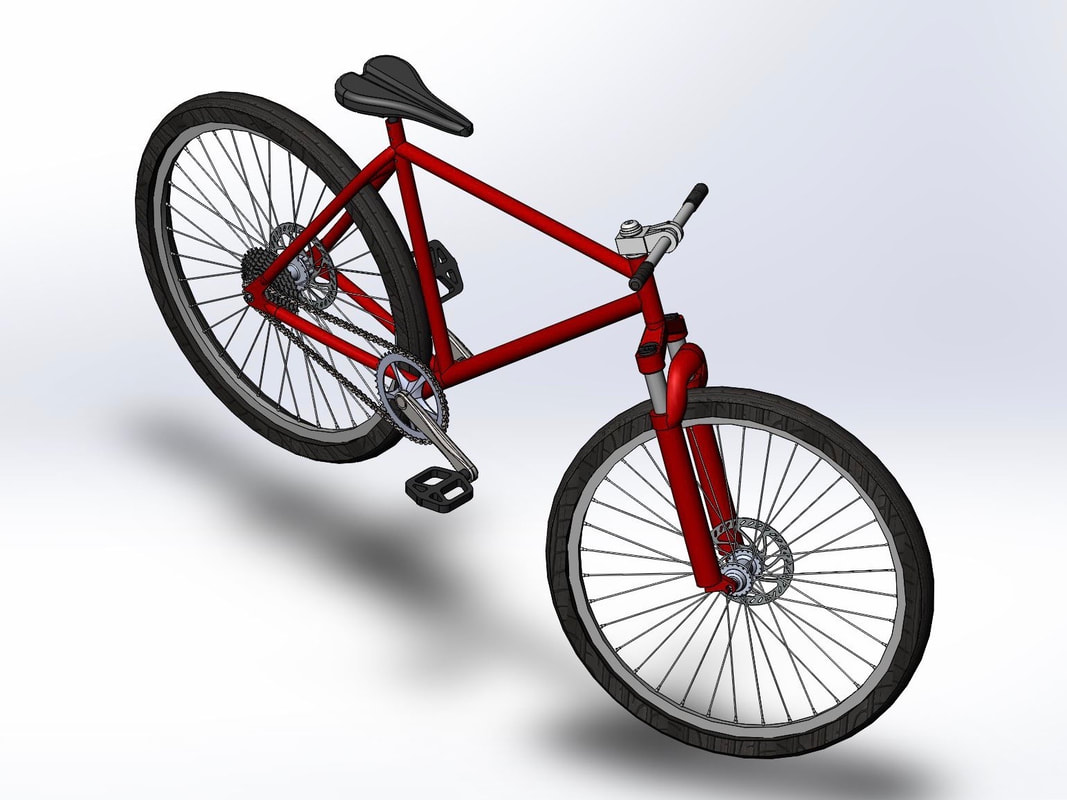
This was a design project to create a bike with similar attributes of that of a real bike.
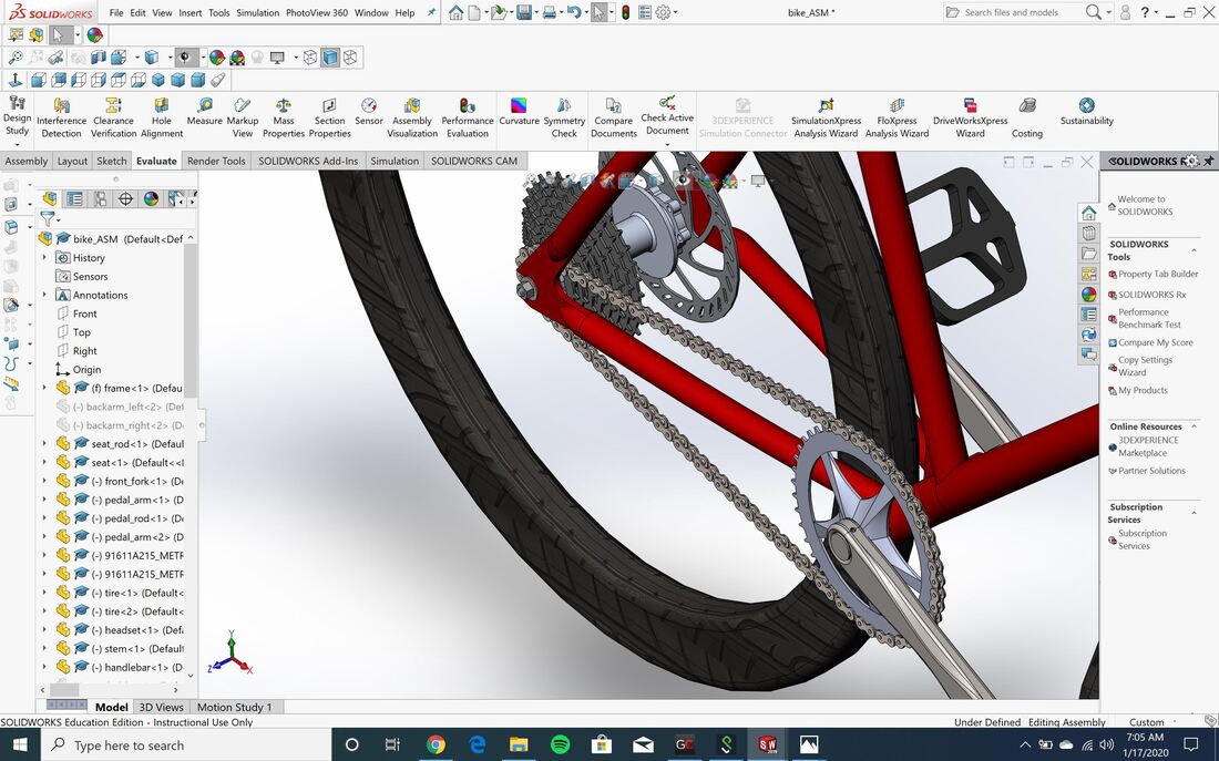
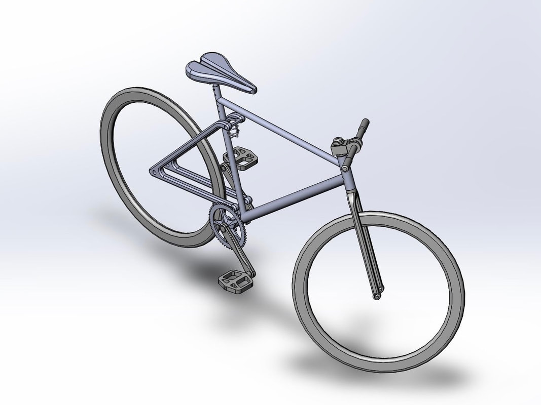
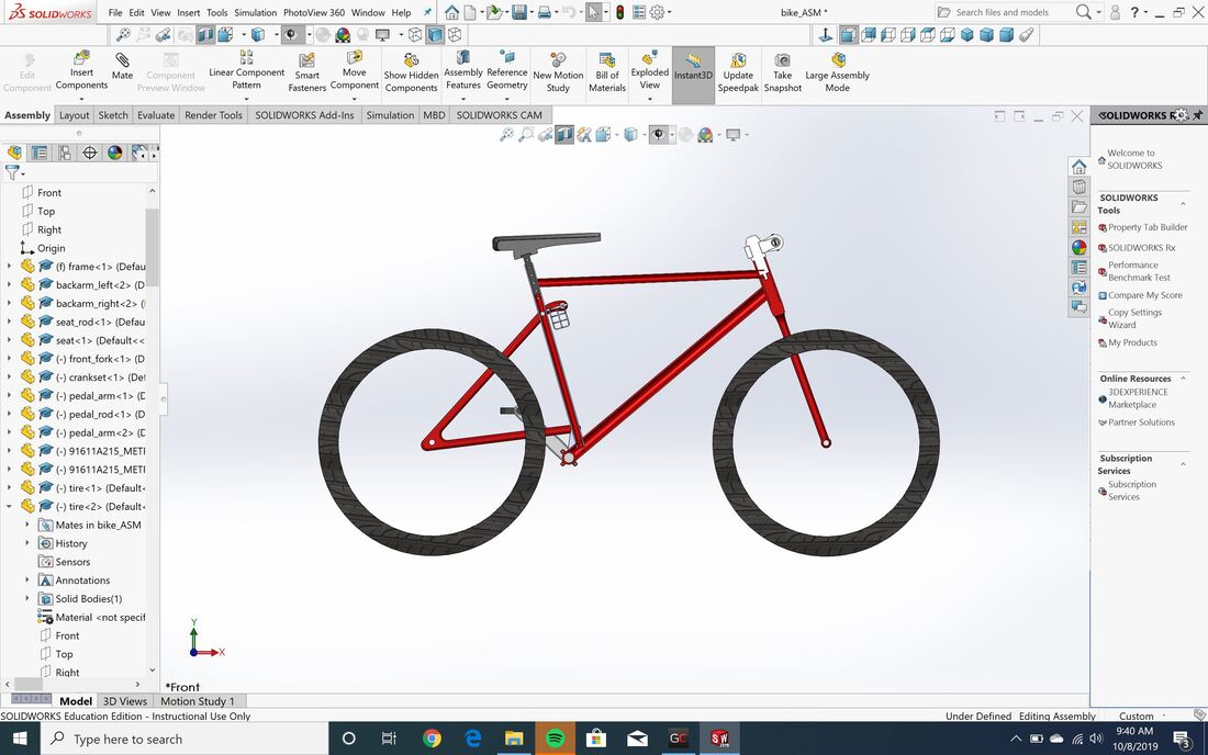
I conducted finite element analysis on the frame and the wheel hubs. To do so, I have designed those parts, along with others, with the same scale as a real bike, modeled off of a mountain bike. Additionally, the bike has a working chain sized to fit around the gears and the chain ring, which I ran a motion analysis on.
I conducted finite element analysis on the frame and the wheel hubs. To do so, I have designed those parts, along with others, with the same scale as a real bike, modeled off of a mountain bike. Additionally, the bike has a working chain sized to fit around the gears and the chain ring, which I ran a motion analysis on.
Finite Element Analysis
Frame:
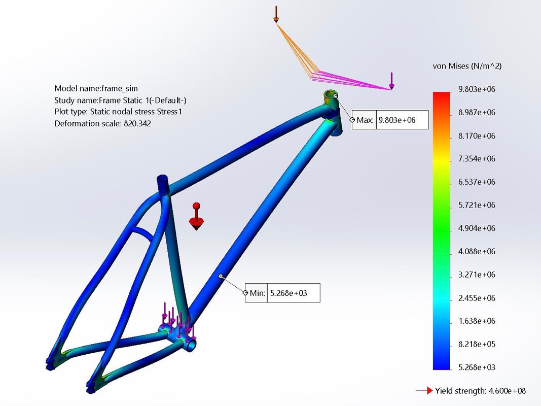
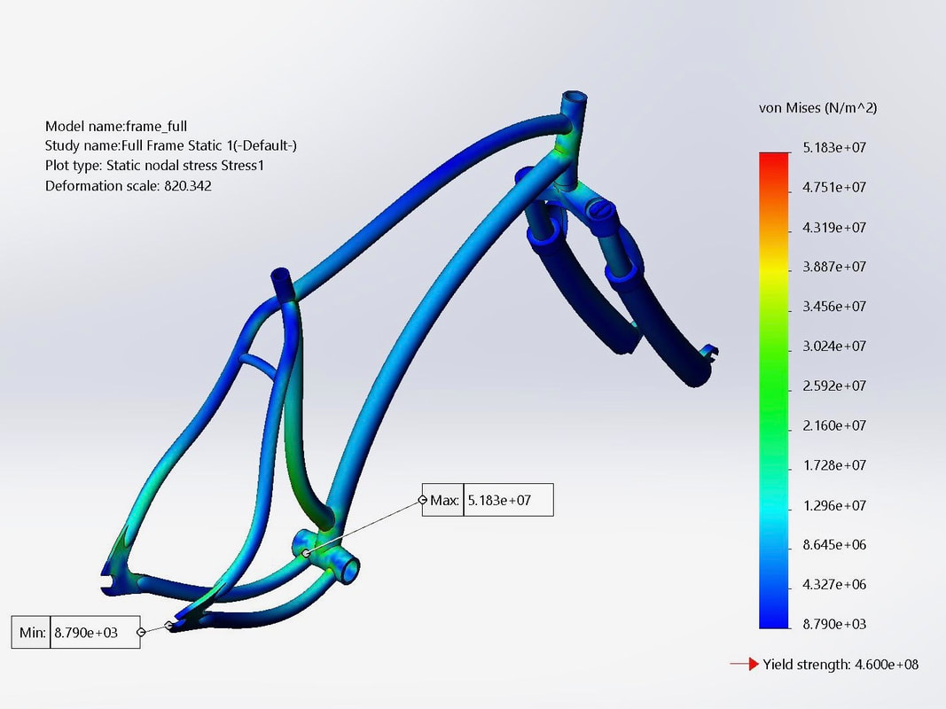
The dimensions of the bike frame fit actual sizes of the back and front wheel hubs and wheels of a standard bike. To conduct FEA on the frame, I used the weight of an average person, 150 lbs, to calculate the loads distributed along the bike.
This includes a bearing load, where 70% of the weight is located at the foot of the bike where the pedals spin in the bottom bracket shell. The other 30% is a remote load, in the position where the handlebar lies with respect to the top of the headtube. These values are 466.48N and 199.92N (total between the two remote loads) respectively. The remote load matches position of the handlebars in the bike assembly.
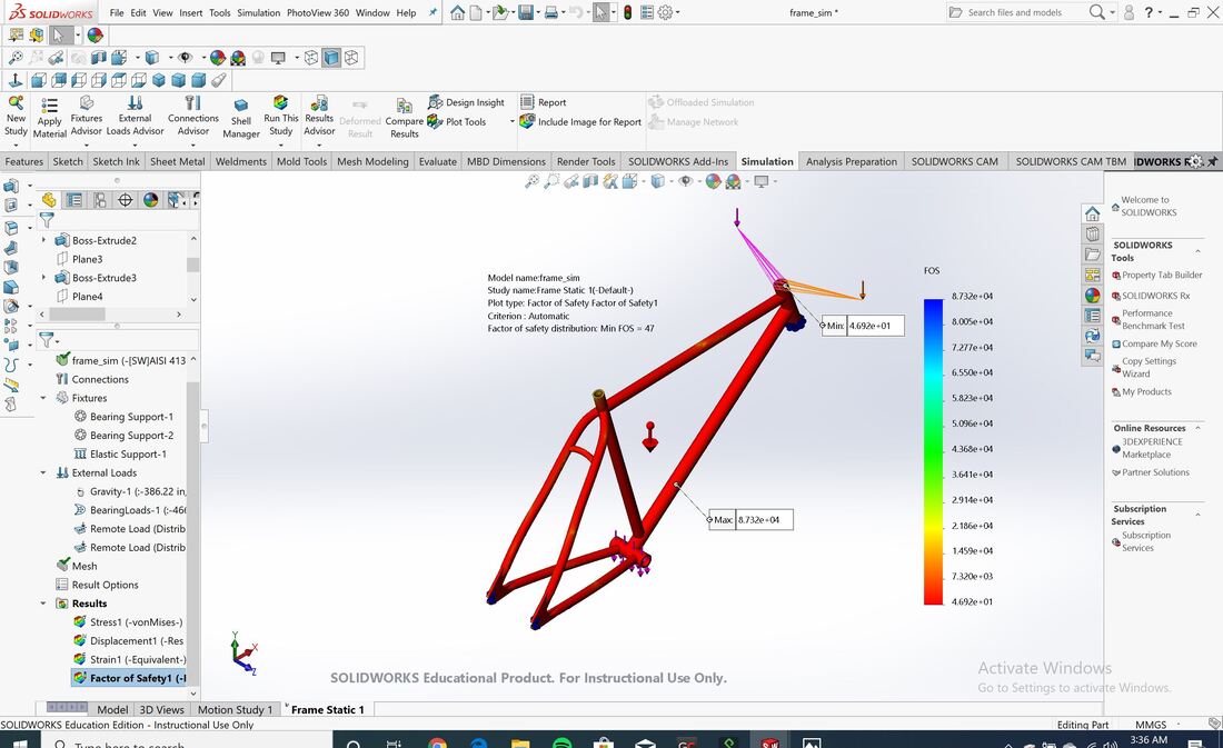
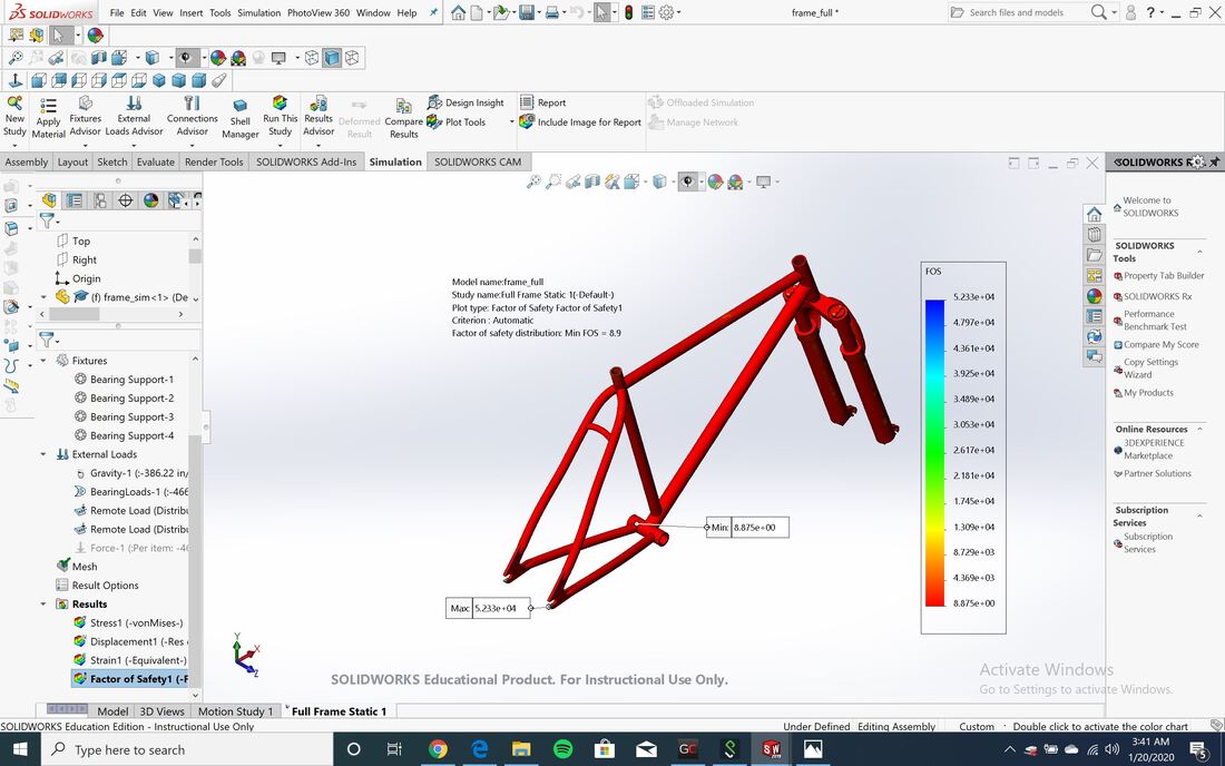
I performed FEA on the frame itself, and on a subassembly of the full frame, which includes the shock absorber and front fork. The factor of safety for the stand alone frame is 47, compared to the full frame which is 8.9. While drastically different, both are strong enough to withstand the load of a human rider. This difference may come from an elastic support versus a bearing support for the front fork, for which the elastic support allows the frame to resist tension and compression.
The dimensions of the bike frame fit actual sizes of the back and front wheel hubs and wheels of a standard bike. To conduct FEA on the frame, I used the weight of an average person, 150 lbs, to calculate the loads distributed along the bike.
This includes a bearing load, where 70% of the weight is located at the foot of the bike where the pedals spin in the bottom bracket shell. The other 30% is a remote load, in the position where the handlebar lies with respect to the top of the headtube. These values are 466.48N and 199.92N (total between the two remote loads) respectively. The remote load matches position of the handlebars in the bike assembly.
I performed FEA on the frame itself, and on a subassembly of the full frame, which includes the shock absorber and front fork. The factor of safety for the stand alone frame is 47, compared to the full frame which is 8.9. While drastically different, both are strong enough to withstand the load of a human rider. This difference may come from an elastic support versus a bearing support for the front fork, for which the elastic support allows the frame to resist tension and compression.
Front and Back Wheel Hubs:
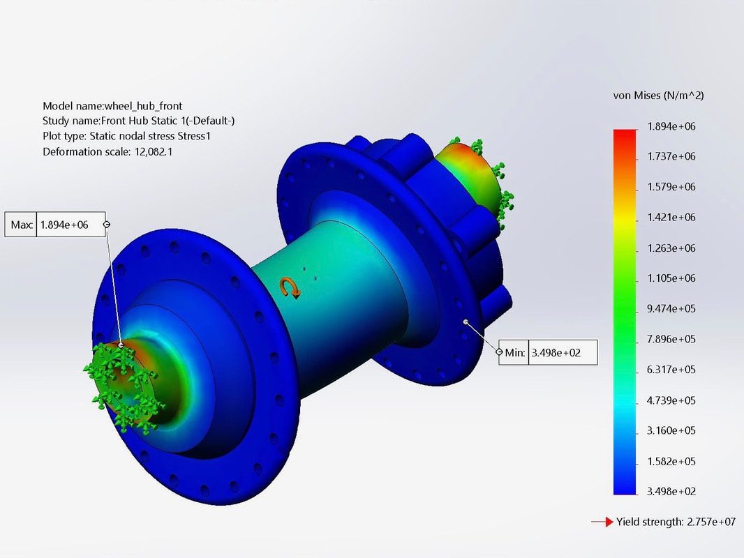
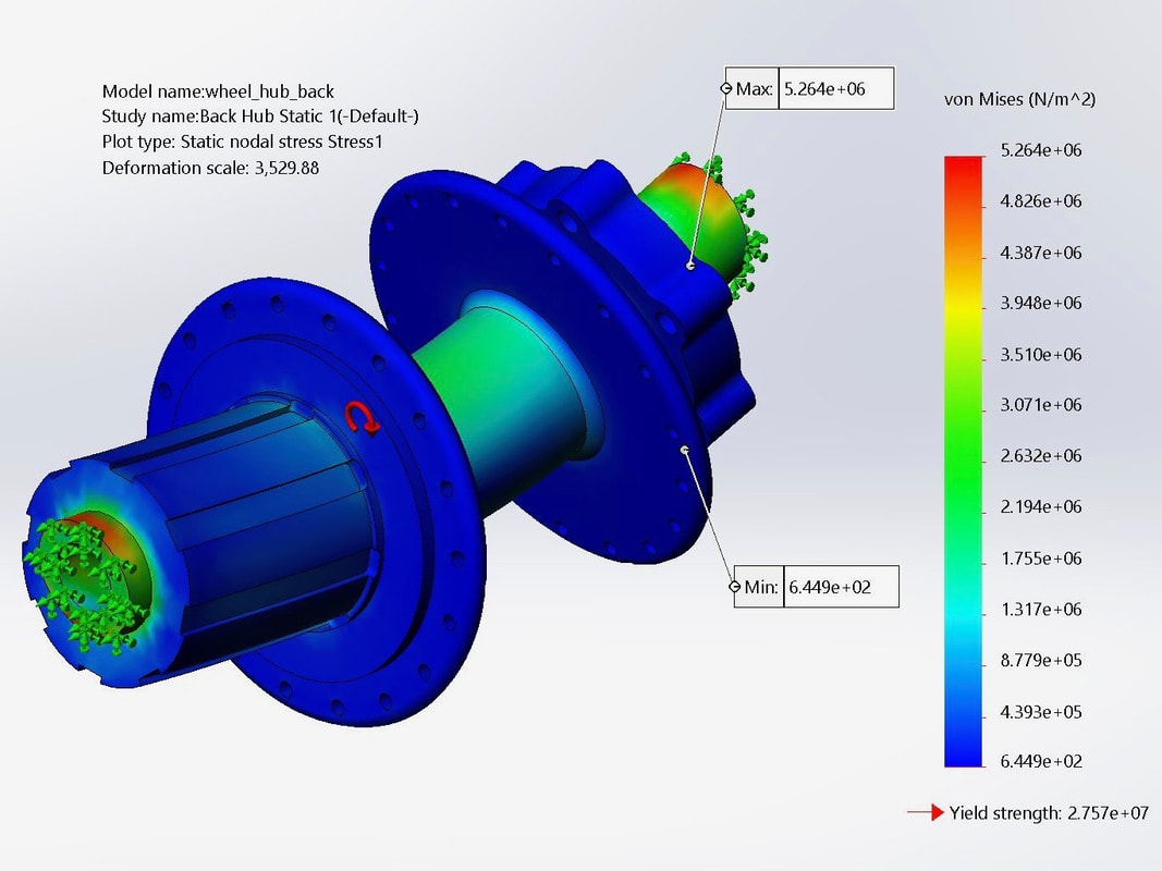
The back wheel hub is 135mm in length while the front wheel hub is 110mm in length. Both have a 12mm axle. I added a force to the axle of the hub corresponding to the 70/30 weight distribution, in addition to a centrifugal force of 10.15radians/sec. This number was determined using an average biking speed of 15mph. Both hubs can adequately handle the load of a person.
The back wheel hub has a larger stress imposed upon it, and more deformation in the center, which can be seen below. One solution is to increase the diameter of the center.
Chain
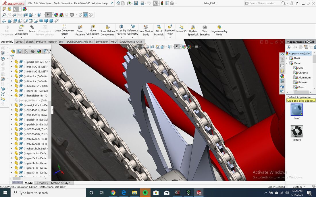
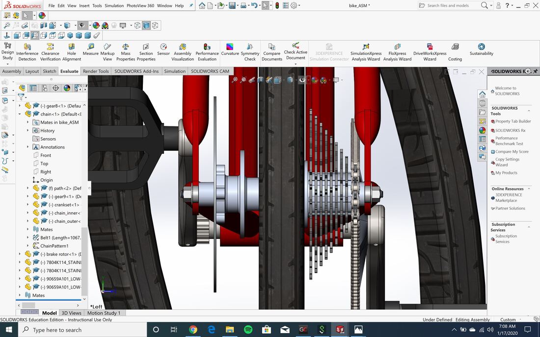
Using the dimensions of a bike chain found online, I first created the inner and outer parts of the chain before modifying the crankset and gears to fit the profile of the chain. I created a subassembly of the chain around the smallest gear and crankset and ran a motion analysis to ensure the chain spun smoothly around the teeth of the gears. I created a nine-speed cogset to mimic a mountain bike.
While I do not have a derailleur, that is what I would design next. My current design cannot shift gears, and is only lined up with the lowest gear. With a derailleur, I would be able to shift gears by moving the chain from one sprocket to another.
While I do not have a derailleur, that is what I would design next. My current design cannot shift gears, and is only lined up with the lowest gear. With a derailleur, I would be able to shift gears by moving the chain from one sprocket to another.
Version 1
Version 1 of the bike was a design project for me to incorporate multiple structures joints, and fastener methods. This was not an accurate representation of a bike, but a design challenge to understand different mechanical structures. Version 2, above, was created with more accuracy.
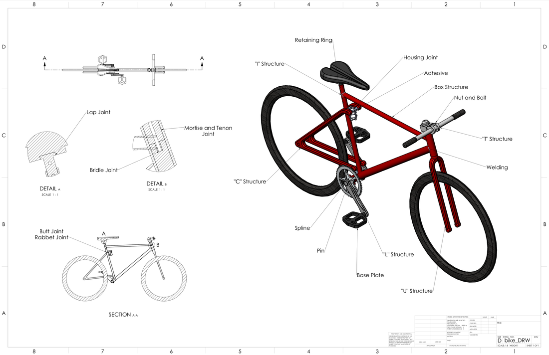
Listed below are the structures, joints, and fasteners I used to create this bike.
|
1. Structures
Base Plate "L" structure "T" structure "U" structure "Box" structure "C" structure "I" structure |
2. Joints
Butt Joint Mitered Rabbet Joint Cross-Lap Joint Housing Joint Mortise and Tenon Joints Bridle Joints |
3. Fasteners
Nuts and Bolts, and Washers Spring Pin Splines Retaining Rings Welding Adhesive |
