Back Brakes
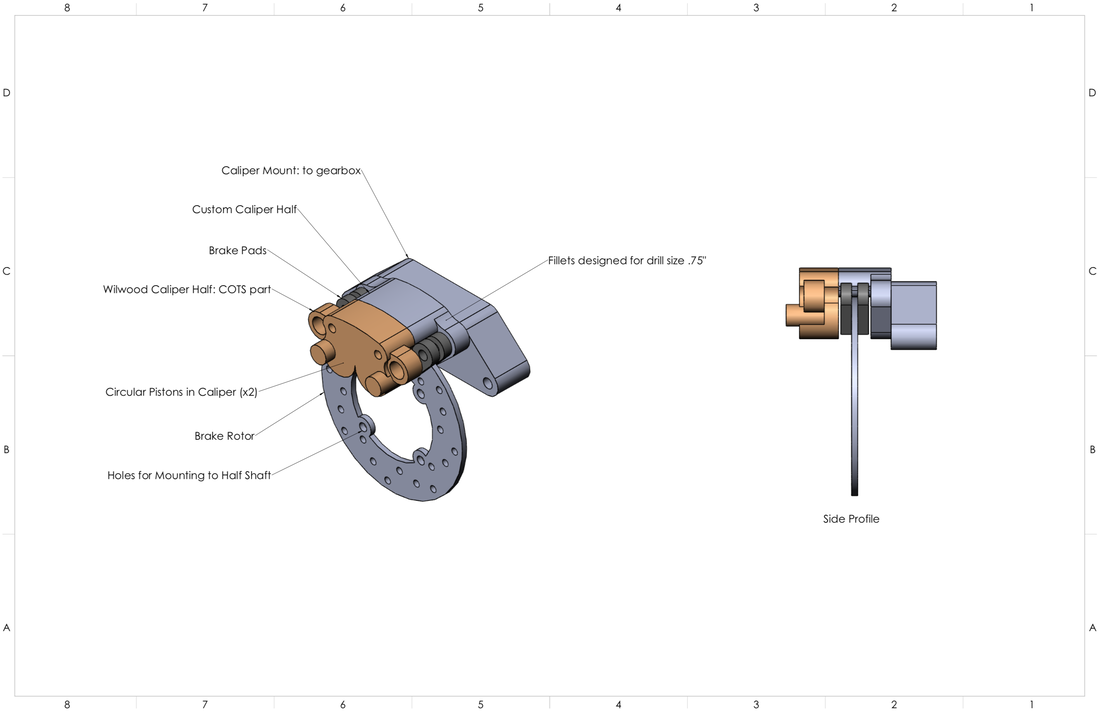
My job for this project was to design the back braking system by redesigning half a caliper (CNC milled) to mount to the gearbox. This was necessary because the caliper we are using is too thick, so it can't fit between the gearbox and the half shaft.
For background, the caliper consists of two halves, one half with the pistons, and one half with the brake line and mounting holes. Redesigning and manufacturing the side with the piston is more difficult than redesigning the mounting half. We also could not use a smaller piston as that would compromise the size of the piston area, which I determined based on force and pressure calculations required to activate the pistons in the caliper. We are using a fixed caliper, where there are two pistons on one side pushing one floating brake pad while the other pad is fixed to the caliper body, as opposed to a floating caliper, where there is one piston on each side simultaneously squeezing the brake pads from either side.
In theory, the floating caliper should work better as the pads wear evenly, as where for a fixed caliper, the sliding pad can seize and the disc wears unevenly, but when our baja team used a fixed caliper, it warped the brake rotor. Our theory as to what went wrong is that our half shaft is not secured in the gearbox so it could float, and because the brake rotor was attached to the half shaft, it would often move out of range of the pistons causing one of the pads to always drag on the side of the rotor. The other problem was that our old brake rotor was made cast iron, which when the brake pads sheared against the rotor, would create graphite dust, which acts as a lubricant, making it more difficult and require more pressure from the driver to brake. While production cars use cast iron brake rotors, they are better equipped to deal with problems such as those or overheating.
The main components to the baja back braking system are:
- caliper
- brake pads
- brake rotor
- caliper mount
Design Decisions:
The three parts to be fabricated, caliper mount, custom caliper half, and brake rotor, are designed to be CNC millable. Fillets are dimensioned to the diameter of the drill bit + 0.03".
The custom caliper half is designed to most similarly represent the COTs half of the caliper.
The brake rotor material was reverse engineered using the front brake rotor material, which worked really well - 1075 spring steel. It's diameter is the size of the larger gear in the gearbox, providing maximum surface area for the brake pads to clamp the rotor. The lightning bolt holes are designed in a 3 / 4 / 3 etc circular pattern so that almost every circular path concentric to rotor are covered with holes for maximum fluid drainage.
The caliper mount is designed with light weighting patterns cut out of the center, while resembling a truss (triangular shape). The triangular shape in trusses are architecturally strong because it allows weight to be evenly distributed along it.
Front Brakes
I helped with the design of the front brakes, where we switched from upper mounted brakes to lower mounted brakes. This was to design a more ergonomic pedal and brake system by providing more foot area in the foot box for members with larger feet. This also allowed us to move the reservoirs to a location better suited for drivers.
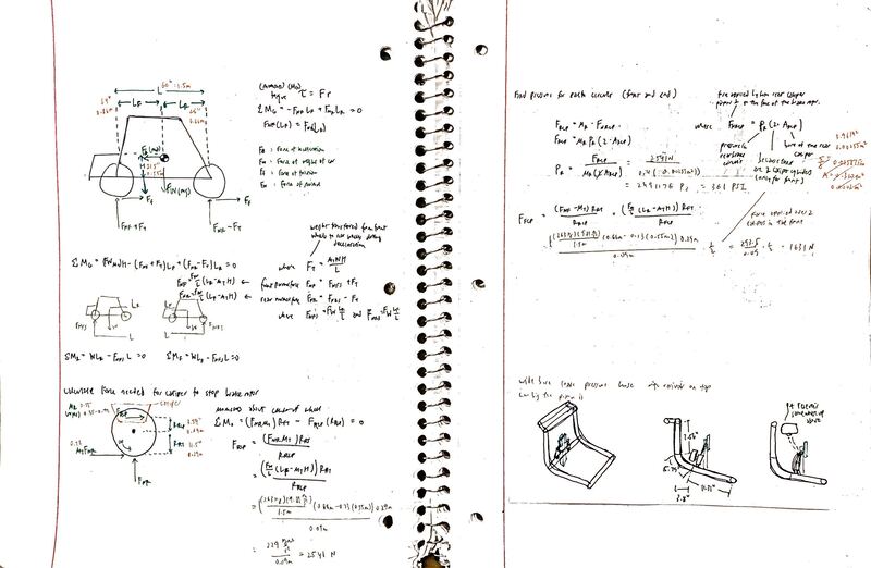
In the process, I analyzed and calculated force loads to find a master cylinder that is suitable to provide enough pressure to the brake rotor. Since we moved to lower mounted brakes, the pressure was critical to find a smaller master cylinder that could be mounted nearly upright to save space, with the correct pressure requirements.
The force calculations included weight transfer from the force that transfers from the back to the front of the car when braking. Force calculations included many sums of moments, and plugging in forces acting on each wheel (front of back). These allowed us to calculate the force needed to stop the brake rotor.
While there are clear benefits to lower mounted brakes, one of the challenges was finding a new way to mount the throttle (bowden) cable from the gas pedal to the back fuel tank motor area. With the lever of the pedal changing, the throttle cable would go from being pulled to pushed if still mounted at the top of the pedal. For the throttle to work, the cable must be pulled, but mounting the throttle cable at the bottom of the pedal would interfere with drivers' feet and be an easy target for puncturing from obstacles slamming through the bottom of the car. This was resolved by mounting it on the side of the pedal and stringing it along the edge of the car.
We also decided to implement cutting brakes this year, which will increase the car's maneuverability by allowing us to drift. Cutting brakes requires two brake pedals, one to brake all wheels, and one to brake the left or right front wheel using solenoids. These solenoids are actuated by pushing a momentary button while turning, which will cut off the brake fluid to the given wheel(s). We have thought about electrical failures with the solenoid valves, by using third solenoid that automatically brakes both the front and back wheels if no button is pressed.
With two brake pedals, it takes half as much pressure to brake the car, which could easier brake the piston, so the brake ratios will be harder to incorporate in the bottom. Front wheels require more force to brake the car, but the force is applied over two calipers, while the back only has one.
